MULTIPLEXER , Design & Implement the given 4 variable function using IC74LS153. Verify its Truth-Table
TITLE: MULTIPLEXER
AIM:Design
& Implement the given 4 variable function using IC74LS153. Verify its
Truth-Table.
LEARNING
OBJECTIVE:
·
To learn about IC 74153
and its internal structure.
·
To realize 8:1 MUX and
16:1 MUX using IC 74153.
COMPONENTS REQUIRED: IC 74153, IC 7404, IC 7432, CDS, wires, Power supply.
IC
PINOUT:
1) IC
74153

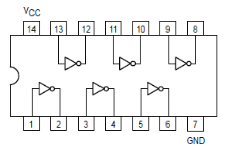
2) IC 7404:

THEORY:
·
Multiplexer is a
combinational circuit that is one of the most widely used in digital design.
·
The multiplexer is a data
selector which gates one out of several inputs to a single output. It has ‘n’
data inputs & one output line & ‘m’ select lines where 2m= n
shown in figure 1. The n: 1 multiplexer can be used to realize an ‘m’ variable
function. (2m= n, where ‘m’ is number of select inputs). Depending
upon the digital code applied at the select inputs one out of the ‘n’ data
input is selected & transmitted to a single output channel.
·
Normally strobe or Enable
(E) input is incorporated which is generally active low which enables the multiplexer
when it is LOW. Strobe input helps in cascading.
Necessity of
multiplexers:
·
In most of the electronic
systems, the digital data is available on more than one line. It is necessary
select single data line from several data- input lines and the data from the
selected line should be available on the output. Under such circumstances we
require a circuit which selects one of the many inputs at a time. This circuit
is nothing else but a multiplexer, which has many inputs, one output & some
select inputs.
·
It is a digital switch.
It allows digital information from several sources to be route onto a single
output line,
·
Multiplexer improves the
reliability of the digital system because it reduces the number of external
wired connections. Therefore, multiplexer is ‘many into one’ and it provides the digital equivalent of an analog
selector switch.

Fig. 1
Block diagram of n: 1 MUX
Types
of MUX:
1.
2:1 MUX 2. 4:1 MUX
3. 8:1 MUX
4.
16:1 MUX 5. 32:1 MUX
4:1 Multiplexer
There
are four input lines (D0 to D3), one output line (Y) and two select lines S0 and
S1. As shown in the function table, the selection of particular input line is
controlled by two section lines.

(a) Logic Symbol (b) Truth Table

(c) Logic Diagram
Fig 2. 4:1
Multiplexer
8:1 Multiplexer
There
are eight input lines (D0 to D7), one output line (Y) and three select lines S0
to S2. As shown in the function table, the selection of particular input line
is controlled by three section lines.

(a) Logic Symbol (b) Truth Table

Boolean Equation:

(c) Logic
Diagram
Fig 3. 8:1 Multiplexer
The
74LS153 Dual 4:1 Multiplexer
·
IC 74LS153 is high speed
dual 4:1 multiplexer IC with common select inputs S0 and S1 (MSB)
and individual enable inputs for each section that is the two 4-input
multiplexer circuits have enables which can be used to strobe the outputs
independently shown in fig 4. When the Enables are high, the corresponding
outputs Y1 and Y2 are forced LOW.
·
The IC 74LS153 can select
data from input under the control of the common select line inputs (S0,
S1). The logic equations for the outputs are shown below.

(a
(a) Internal of IC 74LS153 (b) Truth TableFig4. IC 74LS153
Ex: Design
and Implement 8:1 MUX for given function using IC-74LS153 and verify its Truth
Table. Y (A, B, C) = ∑m (0, 1, 4, 6, 7).
Circuit Diagram:
Truth Table:

Ex: Design and implement the following four variable Boolean function using IC 74LS153 and verify its truth table.
Y (A, B, C,
D) = ∑m (2, 4, 5, 7, 10, 14)
Design Using MSB Bit A:

Fig: Design Table
Circuit Diagram:

Design Using LSB Bit D:

Fig: Design Table
Circuit
Diagram:

Truth Table:

1)
Design given Boolean
equation according to requirement.
2)
Check all the components
for their working.
3)
Give biasing to the IC.
4)
Make connections as shown
in the diagram and observe output.
CONCLUSION:
Comments
Post a Comment