Laboratory Manual (2019 Pattern)

Program Outcomes:
PO1. Engineering knowledge: Apply the knowledge of mathematics, science,
engineering fundamentals, and an
engineering specialization to the solution
of complex engineering problems.
PO2. Problem analysis: Identify, formulate, review research
literature, and analyze complex engineering problems reaching
substantiated conclusions using first principles of mathematics, natural
sciences, and engineering sciences.
PO3. Design/development
of solutions: Design solutions for complex engineering problems and design system components or processes that meet the specified needs with appropriate consideration for the public health and safety,
and the cultural, societal, and environmental considerations.
PO4. Conduct
investigations of complex problems: Use research-based knowledge and
research methods including design of
experiments, analysis and interpretation of data, and synthesis of the information to provide valid conclusions.
PO5. Modern
tool usage: Create, select, and apply appropriate techniques, resources,
and modern engineering and IT tools
including prediction and modeling to complex engineering activities with an understanding of the limitations.
PO6. The
engineer and society: Apply reasoning informed by the contextual knowledge
to assess societal, health, safety,
legal and cultural issues and the consequent responsibilities relevant to the professional engineering practice.
PO7. Environment
and sustainability: Understand the impact of the professional engineering solutions in societal and environmental
contexts, and demonstrate the knowledge of, and need for sustainable development.
PO8. Ethics:
Apply ethical principles and commit to professional ethics and responsibilities
and norms of the engineering
practice.
PO9. Individual
and team work: Function effectively as an individual, and as a member or leader in diverse teams, and in multidisciplinary settings.
PO10. Communication:
Communicate effectively on complex engineering activities with the engineering community and with society at
large, such as, being able to comprehend and write effective reports and design documentation, make effective
presentations, and give and receive clear instructions.
PO11. Project management
and finance: Demonstrate knowledge and understanding of the engineering and management principles and
apply these to one’s own work, as a member and
leader in a team, to
manage projects and in
multidisciplinary environments.
PO12.
Life-long learning:
Recognize the need for, and have the preparation and ability to engage in independent
and life-long learning in the
broadest context of technological
change.
On completion of the course,
student will be able
to:-
1. Identify and prevent
various hazards and timing problems in a digital design.
2. Use the basic logic gates
and various reduction techniques of digital logic circuit.
3. Analyze, design and
implement combinational logic circuits.
4. Analyze, design and
implement sequential circuits.
5. Differentiate between
Mealy and Moore machines.
6. Analyze digital system design using PLD.
|
EXPERIMENT
NO. 1
Aim:
Design and Implement 8:1 MUX using IC-74LS153
& Verify its Truth Table.
Component Used:
74LS153(Dual 4-Line to 1-Line Data
selectors/Multiplexers),Patch Cords.
Procedure:
1.
Place the IC on IC
Trainer Kit.
2.
Connect VCC and ground to
respective pins of IC Trainer Kit.
3.
Implement the circuit as
shown in the circuit diagram.
4.
Connect the inputs to the
input switches provided in the IC Trainer Kit.
5.
Connect the outputs to
the switches of O/P LEDs
6.
Apply various
combinations of inputs according to the truth table and observe the condition of LEDs.
7.
Note down the
corresponding output readings for various combinations of inputs.
8.
Power Off Trainer Kit,
disconnect all the wire connections and remove IC's from IC-Base.
Theory:
Multiplexer
- Multiplexing is the generic term used to describe the operation of
sending one or more analogue or digital signals over a common transmission line
at different times or speeds and as such, the device we use to do just that is
called a Multiplexer.
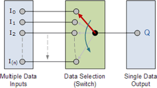
The multiplexer , shortened to “MUX” , is a combinational logic circuit designed to switch one of several input lines through to a single common output line by the application of a control signal. Multiplexers operate like very fast acting multiple position rotary switches connecting or controlling multiple input lines called “channels” one at a time to the output. Multiplexers, or MUX’s, can be either digital circuits made from high speed logic gates used to switch digital or binary data or they can be analogue types using transistors, MOSFET’s or relays to switch one of the voltage or current inputs through to a single output.
Basic Multiplexing Switch

The
rotary switch, also called a wafer switch as each layer of the switch is known
as a wafer, is a mechanical device whose input is selected by rotating a shaft.
In other words, the rotary switch is a manual switch that you can use to select
individual data or signal lines simply by turning its inputs “ON” or “OFF”. So
how can we select each data input automatically using a digital device.
In
digital electronics, multiplexers are also known as data selectors because they
can “select” each input line, are constructed from individual Analogue Switches
encased in a single IC package as opposed to the “mechanical” type selectors
such as normal conventional switches and relays.
They
are used as one method of reducing the number of logic gates required in a
circuit design or when a single data line or data bus is required to carry two
or more different digital signals. For example, a single 8-channel multiplexer.
Generally,
the selection of each input line in a multiplexer is controlled by an additional
set of inputs called control lines and according to the binary condition of
these control inputs, either “HIGH” or “LOW” the appropriate data input is
connected directly to the output. Normally, a multiplexer has an even number of
2 n data input lines and a number of “control” inputs that correspond with the
number of data inputs.
74LS153 is a member of the 74XXYY Ic series. 74LS153 is a fully
complementary, on-chip, binary decoding data selection to the AND-OR gates.
Separator strobe inputs are provided for each of the two four-time sections.
The 74LS153 IC has a wide range of working voltage, a wide range of working
conditions, and directly interfaces with CMOS, NMOS, and TTL. The output of the
IC always comes in TTL which makes it easy to work with other TTL devices and
microcontrollers. The IC 74LS153 is smaller in size and it has a much faster
speed which makes it reliable in every kind of device.

Logic Diagram:

|
Select Lines |
Inputs |
Output |
MUX selected |
|||||||||
|
C |
B |
A |
D0 |
D1 |
D2 |
D3 |
D4 |
D5 |
D6 |
D7 |
Y |
|
|
0 |
0 |
0 |
0 |
X |
X |
X |
X |
X |
X |
X |
0 |
Upper 4:1 MUX |
|
0 |
0 |
0 |
1 |
X |
X |
X |
X |
X |
X |
X |
1 |
|
|
0 |
0 |
1 |
X |
0 |
X |
X |
X |
X |
X |
X |
0 |
|
|
0 |
0 |
1 |
X |
1 |
X |
X |
X |
X |
X |
X |
1 |
|
|
0 |
1 |
0 |
X |
X |
0 |
X |
X |
X |
X |
X |
0 |
|
|
0 |
1 |
0 |
X |
X |
1 |
X |
X |
X |
X |
X |
1 |
|
|
0 |
1 |
1 |
X |
X |
X |
0 |
X |
X |
X |
X |
0 |
|
|
0 |
1 |
1 |
X |
X |
X |
1 |
X |
X |
X |
X |
1 |
|
|
1 |
0 |
0 |
X |
X |
X |
X |
0 |
X |
X |
X |
0 |
Lower 4:1 MUX |
|
1 |
0 |
0 |
X |
X |
X |
X |
1 |
X |
X |
X |
1 |
|
|
1 |
0 |
1 |
X |
X |
X |
X |
X |
0 |
X |
X |
0 |
|
|
1 |
0 |
1 |
X |
X |
X |
X |
X |
1 |
X |
X |
1 |
|
|
1 |
1 |
0 |
X |
X |
X |
X |
X |
X |
0 |
X |
0 |
|
|
1 |
1 |
0 |
X |
X |
X |
X |
X |
X |
1 |
X |
1 |
|
|
1 |
1 |
1 |
X |
X |
X |
X |
X |
X |
X |
0 |
0 |
|
|
1 |
1 |
1 |
X |
X |
X |
X |
X |
X |
X |
1 |
1 |
|
So the truth table of 8:1 MUX will be:
--------------------------------------------------------------------------------------------------------------------------------------------------------------------------------------------------------------------------------------------------------------------------------------------------------------------------------------------------------------------------------------------------------------------------------------------------------------------------------------------------------------------------------------------------------------------------
Comments
Post a Comment